Your first antenna – the half-wave dipole
(Note there is nothing new, this is from the RSGB site)
Many hams’ first choice of antenna is a half-wave dipole. But don’t be misled – just because they are easy to make doesn’t mean they don’t work well. In fact, a half-wave dipole will often outperform many compromise commercial multiband antennas.
Half-wave dipoles are easy to install and erect and are not nearly as likely as end-fed wires to give rise to EMC/interference problems.
As the name suggests, a dipole has two ‘poles’ or sections to the radiating element. In its most common form it is a half-wavelength long at the frequency of operation.
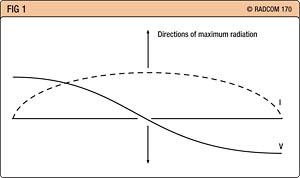
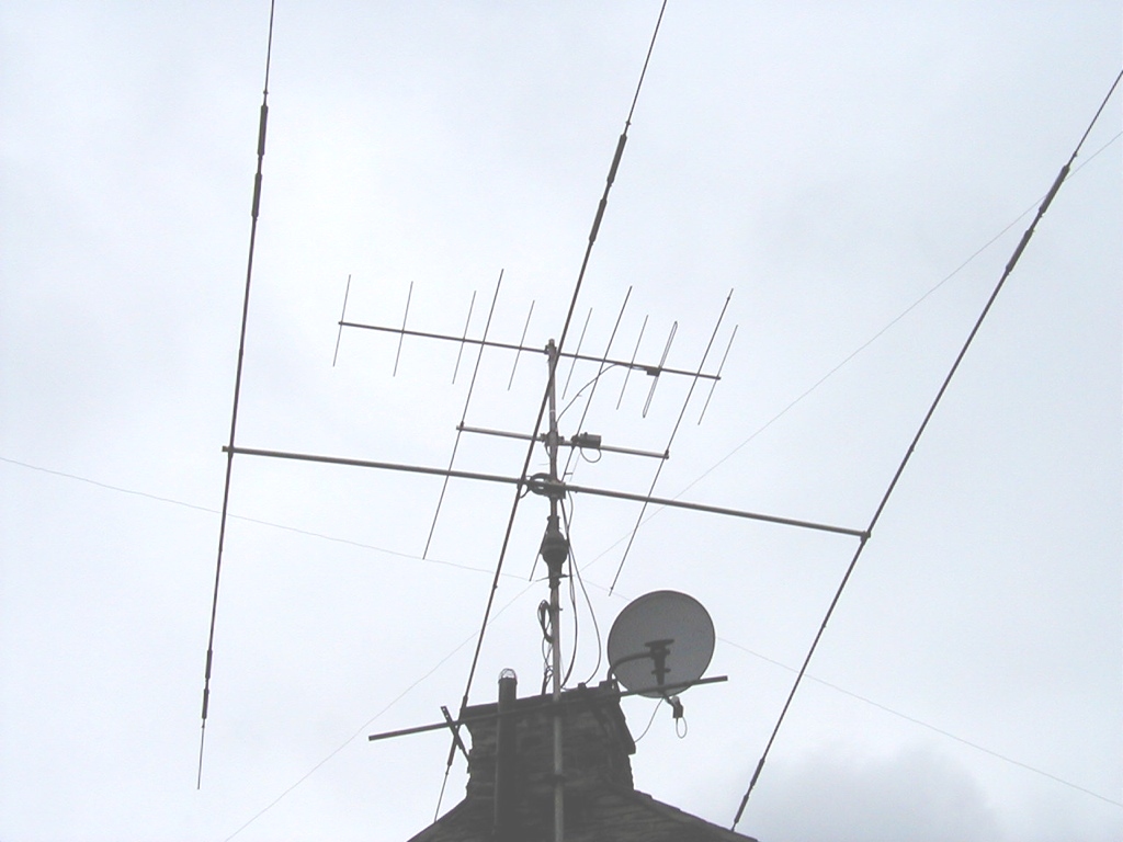
Fig 1 – Current and voltage distribution on a half wave dipole
This is its fundamental resonance, and from looking at the voltage and current waveforms (Fig 1) it can be seen that the voltage is at a minimum at the centre with the current at a maximum.
By feeding the antenna at this point it provides a low impedance feed and a good match to your coax. Normally 50 ohm coax, such as RG213 or RG58 is used as this provides a reasonable match.
The dipole when mounted horizontally radiates most of its power at right angles to the axis of the wire.
In this way it may be possible to angle the antenna to ‘fire’ in the direction where most contacts are wanted, although the dimensions of your garden are more likely to determine what is possible.
It is also possible to operate the antenna at a frequency where its length is three half-wavelengths, or any odd multiple of half-wavelengths long.
This enables a dipole to be used on more than one band of frequencies. For example a half-wave dipole cut for operation on 40 metres (7MHz) will also operate as a three half-wavelength dipole on 15 metres (21MHz), although the SWR will be slightly higher.
Half-wave dipoles used on anything other than their fundamental frequency of operation, or any odd multiple of this, will work, but you will need to use an ATU. A dipole used like this is unlikely to be very efficient and this type of operation should be avoided.
Dipole construction
A dipole is quite easy to construct. The length of a half-wave dipole might be thought to be the same as a half-wavelength of the signal in free space, but this is not quite the case. A number of effects, including the velocity factor of the wire, the length / diameter of the wire used for the radiating element and capacitive end effects, mean that the actual length required is a little shorter.
Without the end effect the length of a dipole could be calculated from the formula length (metres) equals 150 / f, where f is the frequency in MHz. With the foreshortening effects the length can be approximated from the formula: Length (metres) = 143 / f (MHz)
The lengths calculated from this should only be considered as an approximate value – it is best to cut the wire slightly longer than this and then twist the end of the wire back on itself to give the best match.
For a transmitting station one of the easiest ways is to monitor the reflected power on a voltage standing wave ratio, or VSWR, meter.
If operation is tried at different points on the band (taking care not to cause interference) it will be noted that the VSWR is higher at some points than others.
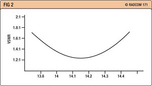
Fig 2: Typical VSWR plot for a half-wave dipole
A plot can be made and should look something like Fig 2. The length of the antenna should be adjusted to give the lowest overall level in the areas of interest of the band. For example if operation is envisaged in the SSB section in the middle of the band, the minimum can be adjusted so that it occurs in this section, whilst still maintaining an acceptable level in other sections of the band. If the minimum VSWR point occurs too low in frequency, the length of the antenna can be shortened.
If it occurs too high in frequency it means the antenna is too short and needs to be lengthened somehow. Putting wire back is not nearly as easy as taking some wire off!
Antenna analysers can also be used and these can give a better indication of the operation of an antenna.
Constructional tips
It is easy to construct a dipole. Basically it is simply a half-wave length of wire cut in the middle.
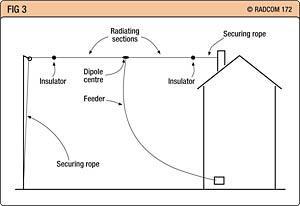
Fig 3: A typical dipole antenna installation
Typically it may be set up something like Fig 3. While this may be the ‘standard’ type of installation, rarely is it possible to make an installation exactly like this, and it is acceptable to make it fit the requirements of the location.
It may be necessary to bend the wire somewhat or have it sloping, for example. These will affect the directional pattern to some degree, but for practical operation it is likely to make little difference.
The other points to note are the ways of fixing the ends of the wire and also connecting the feeder to the centre of the antenna.
Ideally insulators should be used at the ends because these points are at a high voltage point. Small ‘egg’ insulators (Fig 4a) are ideal and they can be bought quite cheaply from antenna specialists.
Egg insulators have the advantage that if they do fracture for any reason they will fall away, but the wire and securing rope will still be looped around each other, meaning that the antenna will not collapse.

Fig 4: Antenna insulators: (a) egg insulator, (b) ‘dogbone’ or ribbed insulator used here as a dipole centre piece
The feeder can be attached to the centre of the antenna in a number of ways. Special dipole centre pieces can be bought. Another alternative is to use a ribbed or ‘dogbone’ insulator.
It is also necessary to remember to seal the end of the coax to prevent moisture entering. If moisture does enter, losses rise considerably, rendering the coax useless.
It is also worth trying to ensure that the end of the coax points downwards to prevent this moisture ingress even if it is sealed.
The feeder can be quite heavy and as a result it is sometimes convenient to anchor the coax to a suitable point to prevent too much weight hanging on the centre of the antenna. This also highlights the point that if at all possible hard drawn copper wire should be used. Copper has a low resistance and its use will result in lower resistive losses, but ordinary copper wire will stretch, and over time it may end up several percentage points longer.
A dipole is what is termed a balanced antenna. In an ideal world a balun should be used with coaxial feeder (which is unbalanced) to make the transition between balanced and unbalanced systems.
The use of a balun will prevent the coax radiating any power or picking up any noise. In many practical situations it is possible to operate the dipole satisfactorily without one, but there may be a slight increased risk of interference if one is not used. Simple baluns can be bought from antenna suppliers, or made.
Inverted-V dipoles
The maximum radiation from a dipole takes place in the centre. Accordingly, this is the most important area of the antenna to keep as high as possible.
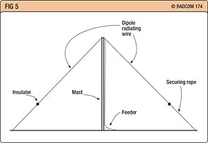
Fig 5: An inverted-V dipole
Coupled with the fact that in many situations it is only possible to have one high mast or high point on the antenna, this often makes an inverted-V dipole (Fig 5) an ideal choice.
The antenna is basically an ordinary dipole, but rather than keeping it horizontal, a single mast or anchor point is used in the centre and the two halves of the dipole are angled downwards away from the central mast.
Although it does alter the radiation pattern, making it almost omni-directional, its basic operation remains the same. In view of its convenience and operational advantages this type of antenna is widely used and is a favourite with many operators.
The main point to note when erecting a dipole is that the lower ends of the antenna should be kept out of reach of people.
The ends of the antenna will have a high voltage when used for transmitting and the installation should be such that it is not possible to touch them. Also, if the ends come down too low you could get ground losses – keep them at least three metres high if possible.
The securing ropes should also be installed so that people cannot trip or stumble over them. A suitably-located tree or bush may help overcome this problem.
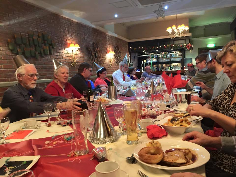 Well, for our Society Christmas Meal we certainly dined in Four Star Style at the Sheffield’s Rutland Hotel, who have very generously sponsored our superb meeting facilities all year long. We ended the year with a bang with some excellent cuisine to die for, with everyone who came along having a really darn fine time.